This chapter addresses hardware issues relating to the vision system. This includes a discussion of power, serial, and video I/O. Many sections are more relevant if you are using the system in stand alone mode, rather than as part of a Pioneer robot. See section Pioneer Vision System Hardware Installation, for information more specific to the Pioneer.
If you choose to write your own code to run on the vision system processor, you can control other hardware directly from the vision system, such as motors and additional sensors. This also allows you to gain access to hardware resources which are not required by the vision system. These resources include spare digital I/O pins, timer lines, and a high-speed synchronous serial port.
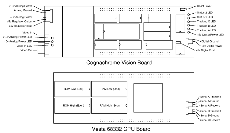
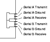
The Cognachrome vision system has two RS-232 compatible serial ports, labeled "A" and "B". These are the primary means for getting data to and from the vision system.
The two serial ports are accessible at the two 3-pin molex connectors side by side on the processor board. For location and pinouts of the two serial ports, see section Cognachrome Vision System Board Diagram. Receive refers to data going to the vision system, and transmit is data coming from the system.
See section Serial Port Pinouts, for information on pinouts of the serial ports of various host machines.
Port A is considered to be the primary port, as it is connected directly to the 68332 processor's hardware asynchronous serial port, and thus takes a minimum of overhead for data transmission and reception. Port A runs reliably at 38400 baud and slower; it may work at higher baud rates but has not been thoroughly tested (please contact us if you wish to use higher baud rates).
Port B is connected to the general-purpose Timer Processor Unit, which runs special microcode to implement asynchronous serial (in addition to the various vision capture tasks it must perform). Thus, while Port B is transmitting or receiving characters, vision system performance may degrade slightly. Port B is only reliable at 9600 baud or slower speeds.
The stand alone mode software (see section Stand Alone Quick Start Guide) uses port A by default. The Pioneer software (see section Pioneer Quick Start Guide) uses port A to talk to the host computer, and port B to talk to the 6811 board which controls the Pioneer robot. Either port A or port B can be used to interactively tune color recognition, change modes and parameters, and to download new executable programs to your vision system.
In all modes except Saphira interaction mode (see section Saphira Interaction Mode), the serial ports use a protocol to multiplex several streams over the same serial line. When using ARC, you do not need to worry about this protocol, as ARC will automatically separate the various streams of interaction into different windows. However, when interfacing to the vision system serial port yourself, you'll need to know how this works.
The protocol is extremely simple and does not support error detection or correction. Each direction on each serial port has an independently maintained current stream. When either the board or ARC receive a stream break character, they interpret the next character as a stream number, and change the current reception stream on that port to be the specified stream number. When the board or ARC want to send a character to a different stream than last time, they send a stream break followed by the new stream number, followed by the data they want to send to that stream. Note that the input side and the output side are completely independent; a stream switch on one side does not affect the other side at all.
The stream break character is decimal 254 (hexadecimal 0xfe). Stream
numbers are in the range of 0 to 31. It is possible to send decimal 254,
but it must be escaped by sending two 254's in a row. This is similar to
the way backslashes are escaped in C strings, and percent symbols are
escaped in printf format strings.
For example, in the following sequence, hi is sent to stream 5, and there is sent to stream 6. Non-printable characters are represented as the hexadecimal value in square braces (i.e., stream break is represented as [0xfe]).
[0xfe][0x05]hi[0xfe][0x06]there
In the next example the characters [0xf8] to [0xff] are sent over stream 7. Notice how [0xfe] is escaped by sending it twice.
[0xfe][0x07][0xf8][0xf9][0xfa][0xfb][0xfc][0xfd][0xfe][0xfe][0xff]
In the stand alone software, the TPUVIS prompt interaction is on stream 3, tracking data is sent over stream 28, and frame uploads are sent over stream 30.
There are two RCA jacks for NTSC video, one for video input, and the other for debugging output. RCA is the coaxial cable standard used by most modern VCR's, TV's, stereo equipment, and camcorders. See section Cognachrome Vision System Board Diagram, for the position of these connectors.
The white RCA jack on the vision system is labeled IN and should be connected to your video source. See section Cognachrome Vision System Board Diagram, for the position of this connector. This channel is terminated by a 75 ohm termination within the vision system, so no other termination is needed.
Unfortunately, NTSC is not an ideal standard for transmitting color information. Due to the encoding of hue and saturation on a 3.58 MHz carrier, noise and/or poor signal quality tend to cause problems in hue and saturation much more than in intensity. Here are things you can do to fight signal degradation:
If you do use BNC cable, use RG-59. Do not use RG-58, because it has a 50 ohm impedance. This is a common mistake, since most computer labs have lots of RG-58 lying around (RG-58 has the correct impendance to be used for Ethernet networking). Most BNC cables have RG-59 or RG-58 labeled on their insulation if you look closely enough, so check before you use.
If you can find a video monitor which can be switched to high-impedance mode, then you can safely view the video on the monitor at the same time as it is input to the vision system. Switch the monitor into high impedance mode--usually there is a switch labeled 75 ohm on one side and Hi-Z (high impedance) on the other. Then, hook up the monitor between the camera and the vision board by using a shielded RCA Y adapter. Hook the Y adapter directly to the input of the monitor--do not use a third piece of cable to connect it. The reason the monitor must be between the camera and vision system, and not have a cable coming from the Y adapter, is to signal reflection (ghosting).
If you do not have a high impedance video monitor (they are fairly rare), do not plug same video signal into both a monitor and the vision system at the same time (if you do, don't complain to us about poor thresholding results). Other video inputs, such as the input to a VCR or camcorder, are usually also 75 ohm terminated, and their use follows the same restrictions as video monitors.
We recommend that you connect a color video monitor in place of your vision board, and look closely at the image. Humans are good at filtering out noise, and you may be used to watching broadcast TV and ignoring the fairly noisy picture. Try to turn off your filtering, and look closely for graininess in the color, or things like color fringes.
If the scene is not lit well, the colors may not look very good in the video image. Try to look at the monitor, and forget what color you know things are supposed to be. If objects on the monitor look indistiguishably brownish to you, they will look indistinguishly brownish to the vision system as well. See section Choosing Lighting.
If your camera has optional white balance adjustment, turn it off. This is important.
White balance correction tries to adjust the hue of the image in real-time to make it look more normal. It turns out that different lighting conditions (incandescent vs. fluorescent vs. sunlight) have fairly different spectra, so the camera tries to compensate for this. But the camera doesn't know what you're pointing at, so it just ends up adjusting the hue until the different colors balance nicely (to the camera's way of seeing).
Unfortunately, white balance correction interferes with color thresholding. If you are seeking an orange beacon with white balance on, the orange the camera transmits will be significantly different depending on the predominant color of the background. Or worse, if the beacon starts filling much of the field of view (say your robot is trying to approach it), the white balance will notice that the picture is too orange and wash out the orange color.
A manual iris is useful when a camera does not have adequate electronic gain control to maintain proper brightness under different lighting conditions. Since the iris will let in the same fraction of light regardless of light levels, cameras with only a manual iris need to be adjusted whenever the light levels change--they cannot adapt on their own.
When the iris is set to let in too little light, the signal will look very grainy. We have seen setups where the iris was inadvertently set to reduce light by 75%, causing the video image to be grainy, thus causing tracking to be quite poor. Opening up the iris fixed the tracking problems.
We recommend that if you have a manual iris, open it all the way, letting the maximum possible light through. If this causes blooming (bright areas start to cause stripes) or fadeout (bright colors start to look white), reduce the iris the only enough to get rid of these artifacts.
The red RCA jack on the vision system is labeled OUT and can be connected to a video monitor. See section Cognachrome Vision System Board Diagram, for the position of this connector. The output on this channel is always black and white, so you do not need a color monitor.
It is very important to watch this monitor while training the system to detect new colors. Also, while it is not strictly necessary for tracking operation, it is useful for monitoring the quality of color tracking.
This channel expects a 75 ohm impedance, but it can handle higher or lower impedances.
Although your vision system was shipped with a power supply, you may need to create your own power supply for it. For example, you may wish to run your system off batteries on a mobile robot base. See section Cognachrome Vision System Board Diagram, for the position of the power connectors.
The Cognachrome system requires the following voltage sources:
(By default, +5v analog is regulated down from the +12v analog. The +12v current requirement can be reduced by supplying the +5v analog yourself. Do not use the +5v digital for this though--noise on the analog supplies can ruin color tracking.)
The analog and digital grounds are not directly connected on the vision board; instead, they are coupled with a resistance of approximately 5 ohms. If you can supply separate voltages without a common ground, this will increase noise immunity between the digital and analog portions of the vision system.
For the location and pinout of the digital power connector, see section Cognachrome Vision System Board Diagram.
There is a small, socketed fuse between the +5v digital connector and the board's +5v supply. It looks a bit like a resistor. If your power supply works, but you do not see light from the red +5v digital power LED (the one next to the digital power connector), check continuity across the fuse.
The most common reason for the fuse to blow is that power and ground are inadvertently shorted by a metallic object touching the male bus interface which protrudes from the top of the vision board. Your system comes with several fuses; if you misplace them or somehow run out, replace with a fast-acting 2 amp fuse (such as DigiKey F828-ND). It is possible to just put a wire in place of the fuse, but this is highly discouraged. It can result in damage to components and board traces. We will not repair any boards which were damaged due to lack of a fuse in this position.
For the location and pinout of the analog power connector, see section Cognachrome Vision System Board Diagram.
The analog subsystem has its own +5v regulator, so in normal usage +12v is supplied to both the +12v Analog Power and +5V Regulator Input pins. Note that the +5v voltage regulator is not automatically connected to the +5v analog line; you must wire the +5V Regulator Output pin back to the +5v Analog Power pin yourself. (See the cables that originally came with your system for an example.)
If you wish to supply separate analog +5v and +12v signals (possibly to reduce the +12v current requirement), you do not need to connect to the +5V Regulator Input or +5V Regultor Output pins at all. Just connect directly to the +12v Analog Power, +5v Analog Power, and Analog Ground pins.
At this time, interfacing to these resources requires writing custom programs for the vision system.
Some configurations of the vision system include an IR sensor. With this feature, the system can be controlled using a Sony TV or VCR remote control.
The system beeps whenever it receives an IR remote command. Each such command is translated into a character, which the vision system processes as if it had been received over the serial port in TPUVIS mode. See section TPUVIS Prompt Mode, for more information on these commands.
The current translation table is given below; remote control equivalents are also given in the documentation for individual commands.