By default, when the Cognachrome Vision System starts operation, it goes into object tracking mode. In this mode, the incoming video stream is digitized to a resolution of 200 by 250, and each pixel is checked for membership in the three independent color look-up tables ("LUT" for short). Connected regions of recognized pixels are merged, and various statistics about the regions can be calculated:
When running the Pioneer software, Saphira configures the tracking mode for each channel by setting persistent variables (see section Saphira Interaction Mode), and the data is uploaded in the form of Saphira packets.
When running the stand alone software, the protocol string provides a very flexible way to configure what data is calculated and transmitted by the board (see section Protocol String).
The protocol string, the color lookup tables, and other configuration information are all stored in the configuration EEPROM.
What you'll read in the following sections are suggestions for how to pick targets to optimize tracking. But don't take all the suggestions as hard-and-fast rules: use them as guidelines to help you optimize your tracking setup. We suggest experimentation to test which suggestions you can get away with ignoring in any given setup.
When deciding what colors to use when marking objects for tracking, the main issue is finding colors which are different from those typically in your environment. We find that highly saturated, "neon" colors often work well. When we set up for tracking in a new environment, we will try several different fluorescent colors and see which one works best for the background and lighting conditions.
When possible, use targets with matte rather than glossy surfaces. Glossy materials are much more affected by the angle the target's surface presents relative to the light source and camera. For example, if you look at a ball that's glossy, you will see reflections of lights, and in bad cases, even be able to see reflections of the surroundings. The big problem is that when glossy materials reflect, they usually reflect the whole spectrum--a reflection of a white light, for example, looks white. This degrades the ability of the color thresholding to cleanly detect such a target.
Most materials are between matte and glossy. This means that the reflection of a white light on most surfaces looks whiter than the material itself, not just brighter--the color saturation goes down. The ideal matte surface does not change color saturation when lighting sources are presented at different angles; it just changes brightness.
We first suggest using lots of light. Most cameras start giving grainy pictures as light levels fall.
Because surfaces are never perfectly matte, color saturation will always depend somewhat on the angle of the target's surface relative to the light source and camera. This causes the worst problems when your lighting is a point source. To minimize the problems of glossiness, ideally, you want to use indirect lighting from many directions.
To avoid shadows across the target, you may want to use lights on the same side of the object as the camera. It is bad to light your target only from behind.
Finally, for some colors and some cameras, we have had slightly better performance illuminating targets with fluorescent light rather than with incandescent light. This appears to be because the spectrum of some incandescent lights contains very little green or blue component, thus reducing the effective range colors in the image.
For other pointers on getting a high-quality video input, see section Video Input.
Once you have chosen a target object, you will want to train the vision
system to threshold for only objects of that color. The vision system has
three color channels: a, b, and c. You can set each
of these channels to threshold for a different color.
Each pixel of the video input is digitized into a 24-bit RGB value. This value consists of 8 bits each of the red, green, and blue components of the light which reached the camera at that point in the image. The goal of the thresholding stage of the vision system is to classify each point in the image as being interesting, meaning that it may be part of a target you want to track, or uninteresting, meaning that it probably is not part of a target. By looking at the debugging video output from the vision system, you can see how various regions of the image are classified at any given time. The interesting parts of the image are shown as being white, and the rest is left black.
Pixels are classified as interesting or uninteresting in hardware by comparing the RGB value of the pixel to a set of values which were defined as interesting when the system was trained. This is done by using the value as an address into a lookup table which maps RGB values into a single bit for each channel: 1 if it is interesting, and 0 if it is not.
The space of possible RGB values contains 16,777,216 distict points. If one bit were stored for every possible value which could come from the video digitizer, this would require over 16 megabits of thresholding information per channel, times 3 channels. Building an inexpensive system with a lookup table this large is not feasible, so a folding scheme is used to reduce this number to a reasonable amount. Instead of defining an arbitrary volume of 3 dimensional RGB space, two 2 dimensional regions of the RG and BG planes are defined to be interesting. The projection of an incoming RGB value into the RG and RB planes must be contained in the interesting region in order to classify that value as interesting.
The set of RGB values in an image of a given object depend on many factors, including characteristics of the particular camera, lighting, and material in any given situation. Human eyes and brains are very good at adapting to changing circumstances. We interpret a given object as appearing constant and distinct from the background in widely varying conditions. However, the actual RGB values which various cameras would provide for the same object in the same set of varying conditions would vary considerably. Therefore, we find that it is best to train the vision system to recognize certain targets in certain situations from empirical measurements. Methods for doing this are described in the next section.
It is possible to train the system to detect an object in a wide range of lighting conditions. In order to do this, you should follow the directions for training on the color of your target, then incrementally train the system through a range of different conditions. However, the range of conditions in which a given target can be accurately distinguished from the background is limited. It must be the case that the range of values acquired for the target does not intersect with the range of values for the background. Otherwise, you may detect background objects when they enter the range of trained target values. This is not necessarily a fatal problem--so long as you can always distinguish the actual target from false positives in the background you should be fine. However, such false positives will make the recognition problem more difficult, and may adversely affect performance.
For example, say that you want to track a light blue target in a dark blue room. For a limited range of lighting levels, this may work fine because the set of values the target and walls occupy may be disjoint. However, when the lights dim, the values for the target may overlap with the values the walls had when the scene was brighter. This problem also arises between more and less saturated colors. For example, an orange object in dim lighting becomes indistinguishable from brown.
There is therefore a tradeoff between the range of lighting conditions and the properties of the background. If everything in the background is sufficiently different from the target, you can train for a wide range of lighting conditions with no loss of performance. However, if aspects of the background are close to the color of the target, you may only be able to get good performance in a small range of lighting conditions.
See section Choosing Tracking Targets, for guidelines on how to choose a target so as to minimize this problem. Then, if it is possible, the best solution is to modify the background to get rid of troublesome elements. Otherwise, you can try to control the lighting. For example, put up curtains if the sun makes the lighting conditions (both in terms of intensity and spectral characteristics) change according to time of day. The final option is to determine a way to recognize which objects are the ones you are interested in, and accept that false positives may occur.
It is possible to train the vision system for a certain color either from TPUVIS mode or, if you are running the Pioneer software, from Saphira interaction mode. The training procedure and commands are the same in either case, but the method of entering them and specifying which channel to affect is different.
In TPUVIS mode, single character commands are typed in the window displaying the TPUVIS prompt (see section TPUVIS Prompt Mode). Which channel is affected by a given command is modal and depends on what the current channel is set to. You can tell what the current channel is by looking at the prompt; the current channel is shown in brackets:
tpuvis[a]>
In Saphira mode, commands are issued by typing at the command line with the
saphira> prompt, then hitting RETURN. Most commands consist of
multiple characters, including a channel specification. See section Saphira Interaction Mode.
The first step in training the system to detect a certain color is to place an appropriately colored training target in the center of the camera's viewing area and sample that color by using the lower case `s' command.
This command will grab a single frame of video, find the color at the exact center of the image, and use that color as the seed color for the training. It will then move out from that point in the image and try to find the outline of the object. If you are using this command from the TPUVIS prompt, a window containing this outline should appear. Once it has found the outline of the object, it will take all of the RGB values from the inside of that area of the image, and classify all of those values as interesting. This set of values will usually be sparse. As the final step, it will fill in the gaps to leave a smooth region.
This step works best when the training target is large in the image, solid colored, convex, and contrasts well with the background. If the training target does not have these characterisics, the outlining step may not work well.
The criteria used for detecting the outline of the training target is
controlled by the diffthresh persistent parameter. This specifies
how different a color can be from the center color and still be considered
to be part of the same object. The default value is 5000. Increase this
value if the system is not classifying a large enough region as belonging
to the training target. Decrease this value if the system is classifying
too large a region as belonging to the object. See section Setting and Storing Persistents, for information on how to change this value.
You may want to try this several times with different values of
diffthresh until you get a good initial training. Don't worry about
getting it perfect--there are more steps to go. However, you should be
sure that the largest block of thresholded pixels in the image corresponds
to the object you are interested in.
In the case that the sample step described above resulted in some of the background being incorrectly thresholded high, you can shrink the edges of the training set by using the `<' (less than sign) command. This will nibble away the edges of the thresholding region, hopefully leaving the training target strong while removing any false positives.
If instead the sample step resulted in no false positives, but only ended up accepting a small part of the target object, you can use the `>' (greater than sign) command. This will increase the size of the thresholding region, while leaving the center the same.
How much is removed from or added to the edges of the thresholding set is
controlled by the color_grow persistent. Setting this value is
somewhat analogous to choosing what grit of sandpaper to use. Increasing
this number makes each command have a larger effect, and decreasing this
number makes each command have a smaller effect. The default value is 5.
See section Setting and Storing Persistents, for information on how to change
this value.
For each frame of the incremental tracking, a small box centered around the
RGB value of the center of the tracked target is added to the training
volume. The size of this box is set by the boxsize persistent
value. The larger this size is, the greater the effect of each incremental
training frame. The default value is 20. If you set this number to be too
large, you may start to get false positives in the background. Use the
shrink command to correct this, then come back to do more incremental
training.
IMPORTANT The stored training values are reloaded from the serial EEPROM on every reset. If you are happy with new settings, you should be sure to issue this command before resetting the board. The persistent values are slightly different. On reset, it will check if the persistent values stored in RAM are still valid. If not, it will use the values in EEPROM to reinitialize the table. However, if the values are still valid, it will not overwrite the values in RAM with the values stored in EEPROM.
The protocol string is a way of customizing how much processing is done on
each channel and what format the data is uploaded over serial while the
system is in tracking upload mode (see section Tracking Upload Mode). It
allows customization without recompilation, so long as the data is sent in
a format supported by the board's version of printf (i.e., ASCII
encoded decimal or hex, or a one- or two-byte value encoded in base 254.)
The protocol string is actually made up of four substrings, the header,
channel A, channel B, and channel C strings. These substrings are set by
using the TPUVIS `p' command (see section TPUVIS Prompt Mode). When
running the default tracking algorithm which uploads data according to the
protocol string, data is uploaded by calling printf with format and
arguments calculated from the protocol strings.
By default, data is sent only for the largest blob in each channel. However, the maximum and minimum number of blobs per channel can be set with the `n' TPUVIS command (see section TPUVIS Prompt Mode). Tracking data will be sent for the N largest blobs, where N will be no fewer than the set minimum, and no greater than the set maximum.
In the case where the maximum and minimum are set to be different values, there will have to be some marker in the protocol strings to let the application determine how many blobs were sent for each channel.
Certain capital letters have special meaning in a protocol string and are used to determine what the arguments to printf will be, and how much processing needs to be done on the given channel. These special characters are removed from the string in order to create the format argument to printf. The following is a list of all the special characters defined so far and the values they generate. The other capital letters are reserved for future use, so you should avoid the use of capital letters for the formatting part of the protocol string.
Note: Currently the blob aspect ratio is not compensated for the aspect ratio of the vision system. This adjustment cannot be done easily (in the general case) as a post-processing step. We plan to allow users to input calibration data and have the system aspect ratio automatically compensated in a future release.
Note: Currently this angle is not compensated for the aspect ratio of the vision system. This adjustment cannot be done easily (in the general case) as a post-processing step, so we will soon release a new version of the software that will allow users to input calibration data and have the aspect ratio automatically compensated.
The board's version of printf has an additional nonstandard feature.
You can use the `%w' printf code to print a value in base 254, using
either one or two bytes. This is useful because it will have a fixed
number of bytes regardless of ARC's stream protocol. See section RS-232 Port Protocol, for more information.
Like standard printf formatting codes, you can specify a field width
by placing a number between the `%' and the `w'. For example,
%1w specifies a field width of 1 character. Unlike standard
printf formatting codes, the %w code treats the field width
as an exact number of bytes to send, rather than just a minimum. This is
good because it means that the %w code will produce a fixed number
of characters regardless of the value. If the field width is unspecified,
the default width of 2 characters is used.
The following table summarizes the strengths and weaknesses of using various encoding methods for transmitting serial information for machine consumption.
See section The %w printf Code, for more information on the %w formatting
code. Refer to any C reference manual for more information on the other
formatting codes.
Flags, field width, precision, and size modifiers can be specified between
the `%' and the formatting code. These are supported by the version
of printf on the processor board. You should not need to use the
size modifier flags (`l', `L', or `h') as all of the
arguments to printf generated by protocol codes are cast to be 4
byte integers (which is the default if no flag is specified).
Note that in accordance with the ANSI specification, the field widths
parameter only specifies a minimum and not a maximum field width. For
example, if a number larger than 255 were formatted using the %02x
code, it would contain more than 2 characters. See section Protocol Codes Summary for information on the range of values each protocol code
generates.
As well as specifying the upload format, the protocol string is also used to determine how much processing should be done on each channel. Only the minimum amount of processing required to calculate the information requested in the protocol string is done. The processing level is determined by which formatting code in the current protocol string appears lowest on the following list.
In this example, we want to track the positions of each of two orange balls. Channel A is trained to detect orange, and the other channels are not used. The maximum number of blobs is set to be 2 using the `n' TPUVIS command (see section TPUVIS Prompt Mode). The tracking data shown is for the following static sample image.
If you do not see this image in color, you can see it at:
`http://www.newtonlabs.com/cognachrome/cognachrome_5.html#protocol_example1'.
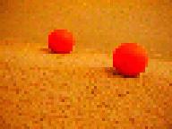
For nice, human readable output, you could use the TPUVIS `p' command (see section TPUVIS Prompt Mode) to set the protocol string to the following:
Header: "frame %3dG:\n" Channel A: "\ta: diameter %3dN, cg (%dC,%dR)\n"
Channel B: "" Channel C: ""
Using the `r' TPUVIS command (see section TPUVIS Prompt Mode) to test the new protocol string on the sample image yields:
frame   1:
        a: diameter  41, cg (189,115)
        a: diameter  31, cg (105,82)
frame   3:
        a: diameter  41, cg (189,115)
        a: diameter  31, cg (106,82)
frame   5:
        a: diameter  41, cg (189,115)
        a: diameter  31, cg (105,82)
frame   7:
        a: diameter  41, cg (189,115)
        a: diameter  31, cg (106,82)
frame   9:
        a: diameter  41, cg (189,115)
        a: diameter  31, cg (106,82)
Note that the frame numbers show that the data was not sent for every frame. Video contains 60 frames per second, and the frame number reported by the `F' and `G' commands count every frame. Using this protocol string yields around 80 characters of data uploaded per frame.
At a baud rate of 38400 baud, you can send data at a rate of 3840 characters per second (baud measures bits per second, there are 10 bits per character). This works out to 64 characters taking a full sixtieth of a second--the same amount of time which it takes to receive a full frame of video. Therefore it is not possible to send the data for every frame using this protocol string. In this situation, the system skips sending data for frames until the serial buffer is clear. The alternative would have been to send every frame with increasing delays until the serial output buffer filled, then throw out the overflow characters. This decision was made in order to minimize latency, which is a very important factor in stably controlling dynamic systems.
If you have a program parsing the data stream, you do not have to format the data in a way which a human would find easy to read. Instead, you want to make the information easy for a program to interpret, and you want to pack a large amount of information into a small number of bytes of transmission data. In this example, the same information is sent in the same order as in the human readable example, but it is intended to be read by a machine.
The highest information density can be achieved by using the %c or
%w binary formatting codes (see section The %w printf Code). However,
the %x hexadecimal formatting code has some advantages, even though
it requires approximately twice as many characters:
a to f
for framing and never confuse them with the numbers.
This problem is much more difficult when using the %c binary
formatting code because there are no characters which are guaranteed not to
appear as part of a number. Also, while it is possible to use 255 as a
unique framing character when using the %w format code, the
processing of the protocol string does not yet support numeric literals
(i.e. \377 for 255). Therefore there is no convenient way for 255 to be
encoded into the protocol string. This will be fixed in future versions.
In this example, hexadecimal encoding is used. Also, you will notice that
the full formatting specification is %02x. The `0' (zero)
specifies that zeroes should be used for padding instead of spaces. The
`2' specifies that the minimum field width is 2 characters.
See section Summary of printf Formatting Codes, for more information.
Only the `G', `N', `C', and `R' protocol codes are used in this example--all of which are specified not to exceed 255 (see section Protocol Codes Summary). Therefore the data for each object will contain a constant number of characters.
This example uses the TPUVIS `p' command (see section TPUVIS Prompt Mode) to set the protocol string to the following:
Header:         "$%02xG"
Channel A:      "#%02xN:%02xC:%02xR"
Channel B:      ""
Channel C:      ""
Using the `r' TPUVIS command to start tracking with this protocol string yields the following results. Carriage returns have been added here to make it more readable. The actual data sent contains no carriage returns.
$01#29:bd:73#1f:6a:52
$02#29:bd:74#1f:6a:53
$03#29:be:74#1f:6a:52
$04#29:bd:74#1f:6a:53
$05#29:be:74#1f:6a:52
$06#28:be:74#1e:6a:52
$07#29:bd:73#1f:6a:52
$08#28:bd:74#1f:6a:53
$09#29:bd:73#1f:6a:52
$0a#29:bd:74#1f:6a:53
Note that while frames were skipped in the human readable example, all frames are present in this example. This is because only 21 characters are being sent per frame. It only takes 5 milliseconds to send 21 characters at 38400 baud. Each frame takes about 17 milliseconds, so it is possible to send all of the data without skipping any frames.
In this example, we want to track the positions of each of two orange balls; the position, aspect ratio, and angle of a blue piece of cardboard; and the position, and bounding box dimensions of a dark green serial adapter. Channel A is trained to detect orange; B is trained to detect blue; and C is trained to detect dark green. The maximum number of blobs is set to be 2 for channel A, and 1 for channels B and C. The tracking data shown is for the followint static sample image.
If you do not see this image in color, you can see it at:
`http://www.newtonlabs.com/cognachrome/cognachrome_5.html#protocol_example2'.

The protocol string is set up to be the following:
Header:         "$%02xG"
Channel A:      "#%02xN:%02xC:%02xR"
Channel B:      "*%02xN:%02xC:%02xR:%02xS:%02xA"
Channel C:      "&%02xN:%02xC:%02xR:%02xW:%02xH"
Using the `r' TPUVIS command to start tracking with this protocol string yields the following results. Carriage returns have been added here to make it more readable. The actual data sent contains no carriage returns.
$01#21:50:a8#1d:86:a2*23:7b:74:64:47&1d:c5:bd:22:25
$03#21:50:a7#1d:86:a2*23:7b:73:64:47&1c:c6:bc:21:26
$05#22:50:a8#1d:86:a2*23:7b:74:64:47&1c:c6:bd:21:25
$08#22:50:a7#1d:86:a1*23:7b:74:64:47&1c:c6:bb:1f:24
$0a#22:50:a7#1d:86:a1*23:7b:75:64:47&1c:c6:bc:21:26
You can see that frames were skipped in this example. Here 51 characters are sent per frame, so it takes 13 milliseconds per frame at 38400 baud to upload the information. Since each frame takes about 17 milliseconds, it would be possible to send this much serial data without missing any frames. However, processing three channels with angle information takes long enough that some frames must be skipped. See section Multiple Channel Tracking Plus Angle Performance Example, for a more in-depth analysis of the calculation time used by this example.
You can use the `m' TPUVIS command to obtain rate and latency information when no serial data is sent (see section Debugging and Miscellaneous Detail). Which channels are acquired and how much processing is done for each is set by the protocol string. This is so that the information can easily be compared against tracking performance in normal operation.
Each frame for which the data is available is processed as usual, but no data is sent over the serial port. Instead, the amount of time which passed between when the data started to become available and the time when the processing was completed is recorded. A fixed number of frames are processed, and the number of frames which had to be skipped is calculated. The output of this command is formatted in the following manner.
tpuvis [a]> m Missed M over N frames: avg latency L ms
The system has two edge acquisition buffers. Generally one is being filled while the other is being processed. When a new frame starts, whichever buffer is not being processed is filled with the incoming data. If the most recently processed buffer has not been released yet when it would be time to refill it, the buffer which was most recently filled will be refilled, and data for the previous frame will be lost.
The camera provides 60 frames per second, so the total time during which frames were acquired is T = (N+M)/60 seconds. During this time N frames were processed. This leads to an output frame rate of R = N/T, or R = 60*N/(N+M) Hz (frames per second).
From this equation, you can see that if zero frames are missed, R = 60 Hz. As more frames are missed, the frame rate degrades smoothly.
Another way to look at the data uses the latency figures. It takes 17 ms from start to finish for a single frame to arrive from the camera. It then takes some additional time for the system to finish processing the information, and release the buffer to be refilled. This extra time is E = L-17 ms. If E > 17ms, then frames will definitely be missed. It is difficult to say more than that about the relationship between latency and frame rate.
The following examples give performance specifications for the same scene as the multiple colors protocol string example (see section Multiple Colors Protocol String Example) at different levels of processing.
Processing the scene and calculating the largest blobs on the first channel only yields the following:
tpuvis [a]> m
Missed    0 over  500 frames: avg latency   20 ms
Here M = 0, so the frame rate is a full 60 Hz. It was possible for the acquisition buffer to be switched every time, so no data was lost.
Processing the same scene and calculating the center of the largest blobs on all three channels without calculating angle provides the following results:
tpuvis [a]> m
Missed    0 over  500 frames: avg latency   23 ms
Again M = 0, so the frame rate is a full 60 Hz. Both of the last two examples would result in the same frame rate, but this would have slightly more latency than the previous one.
Here the protocol string from the protocol string example (see section Multiple Colors Protocol String Example) was used. The center of the largest blobs on all three channels, plus the aspect ratio and angle on channel B were processed:
tpuvis [a]> m
Missed  249 over  500 frames: avg latency   29 ms
Here M = 249 and N = 500. The frame rate R = (60*500)/(500 + 249) = 40Hz. This tells us that the processing buffer was not ready to be refilled about a third of the time. This was caused because the angle and aspect ratio calculations are quite expensive compared to just tracking the center of the objects. In this case, the added time for computing angle on one channel was 6 ms--a 26% increase.