Reactor Pressure Vessel (RPV) Measuring Robot
Designed for Use in BWR Vessels
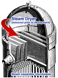
The Upper RPV Measuring Robot enables BWR reactor operators to precisely scan, image and measure the sidewall and peripheral horizontal areas above the steam separator. The RPV robot, developed and manufactured by Newton Labs, is deployed during an outage in a boiling water reactor (BWR) after the steam dryer has been removed. The system provides precise, non-contact measurements and high resolution imaging of features on the vertical sidewall and the outer periphery horizontal areas. |
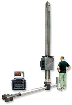
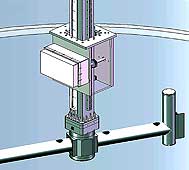
The production version of the Upper RPV Robot- composed of
mast, gearbox, boom, measuring head and control unit (shown to scale). |
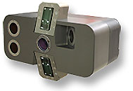
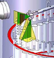
The measuring head, attached to the end of an extendable arm, houses multiple sensors, an underwater laser scanner and multiple high-resolution imagers. The counter-balanced camera arm is attached to a rotational gearbox hub at the end of a 15 ft. (4.6 m) tall mast which is controlled by a vertical gearbox. The robot is capable of precision movement in elevation, rotation and features a two-position extension of the camera arm. |
|
Deployment
Once onsite for a BWR outage and after removal of the steam dryer, the vertical operation gearbox, mast and arm of the RPV robot is secured and centered over the open reactor on an owner-provided structure approximately 4 ft. (1.2 m) above the vessel flange.
Operation Overview
In operation, the robot begins at zero degrees and full height and begins to rotate, collecting and storing data as it goes. Once the initial upper cycle is complete, the mast gearbox lowers the mast and boom to the next vertical index position to repeat the scanning/data collection cycle. This continues until the entire vessel and outer upper perimeter of the horizontal steam separator is imaged.
Features
- Maps the inner diameter of the RPV in the area of the dryer
- Measures the maximum diameter of the steam separator guide ring
- Locates the four lifting lugs in azimuth, radius and height to RPV flange
- Returns an image of the shroud lifting lugs and the steam separator guide ring below the standpipe tops in the outer perimeter
- Measures the vertical distance of the highest steam separator standpipes to the RPV flange
- Locates the four steam dryer brackets in azimuth and radius and vertical distance to the flange
- Capture the topographic three dimensional data from the top perimeter of the steam separator standpipe and swagelock caps
- The system is modular and capable of being decontaminated, serviced and or repaired with the least complexity possible
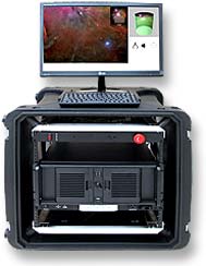
- The deployment device is powered and controlled via a Newton control box and custom user interface
- The RPV robot can be economically reconfigured for different diameter BWR vessels by simply changing the length of the measuring head boom