Printed in AI Magazine, Spring 1997,
Volume 18, No. 1
AI Magazine is published by the American
Association for Artificial Intelligence (AAAI).
Dynamic Object Capture using Fast
Vision Tracking
Randy Sargent
Bill Bailey
Carl Witty
Anne Wright
This paper discusses the use of fast (60 frames
per second) object tracking using the Cognachrome Vision System,
produced by Newton Research Labs. The authors embedded the vision
system in a small robot base to tie for first place in the Clean
Up the Tennis Court event at the 1996 Annual AAAI Mobile Robot
Competition and Exhibition, held as part of the Thirteenth National
Conference on Artificial Intelligence. Of particular interest
is that the authors’ entry was the only robot capable of
using a gripper to capture and pick up the motorized, randomly
moving squiggle ball. Other examples of robotic systems using
fast vision tracking are also presented, such as a robot arm
capable of catching thrown objects and the soccer-playing robot
team that won the 1996 Micro Robot World Cup Soccer Tournament
in Taejon, Korea.
|
The place: The
1996 Annual AAAI Mobile Robot Competition and Exhibition, held
as part of the Thirteenth National Conference on Artificial Intelligence
(AAAI-96) in Portland, Oregon. The goal: To demonstrate
a robot that autonomously collects fifteen tennis balls and two
quickly and randomly moving, self-powered squiggle balls, and
delivers them to a holding pen within the allotted time.
Our entry: A
robot covering less than a square foot (or .09 m2)
floor space, with a gripper slightly larger than a single ball,
and a high-performance vision system. Our robot collected all
the balls, and received a perfect score for the contest. We attribute
most of our success to the Cognachrome Vision System, a portable,
high-performance system capable of very fast (60 frames per second)
tracking of many objects distinguished by color (see
http://www.newtonlabs.com/cognachrome/). Our perfect score
tied us for first place with another team, led by Sebastian Thrun
of Carnegie Mellon University, whose robot also used the Cognachrome
system. |
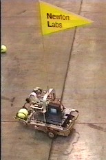 Figure 1. M1 carries a tennis ball
during its winning run at AAAI '96
Figure 1. M1 carries a tennis ball
during its winning run at AAAI '96 |
1. The Robot Hardware
The prototype robot we used for this contest
is named M1 (figure 2). M1’s basic frame is constructed
from stock aluminum extrusion to form an open cage 6 1/2"
by 8" by 2 1/2" high. Connected to this frame are two
driven wheels (forming a simple differential drive); a caster
wheel; eight infrared proximity sensors;eight contact sensors;
a gripper; batteries; a small video camera; and the vision system,
which also serves as the robot’s controller. |
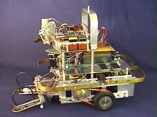
Figure 2. Our robot, M1 |
1.1 Sensors
Sensors on the robot fall into three categories:
(1) vision, (2) infrared obstacle detection, and (3) contact.
1.1.1 Fast Vision Tracking with the Cognachrome Vision System
The robot’s primary sensor is Newton
Research Labs’ Cognachrome Vision System (figure 3). This
system allows very fast (60 frames per second), accurate tracking
of many objects that are distinguished by color. Tracking by
color is a natural for this contest: the tennis balls are bright
yellow, and the squiggle ball is red. We mark our goal area with
a blue square. For our robot, fast position data is instrumental
for quickly and accurately servoing to follow and capture the
moving squiggle ball with a gripper that is only marginally bigger
than the ball itself. M1 uses a small videocamera with a wide-angle
lens, mounted on a single stepper motor to permit camera tilt.
Camera pan was provided by pivoting the robot itself. |
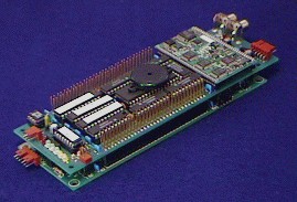
Figure 3. The Cognachrome Vision System |
1.1.2 Infrared Obstacle Detection
To assist in object or wall avoidance, an
array of narrow beam infrared light-emitting diodes (LEDs) are
driven one at a time with a modulation of 40 kHz. The reflected
IR is detected with a pair of standard IR remote control detection
modules (Sharp GP1U52X or equivalent). The directions of the
eight LEDs are distributed on a horizontal plane over the forward
180 degrees, with the two IR detectors facing the two forward
quadrants. Each LED is fired in turn, and the resulting detector
data are latched, providing eight bits in parallel (one bit per
direction) to the controlling processor. This system provides
reliable obstacle detection in the 8 to 12 inch (20-30 cm.) range.
Although the system provides only yes-no information about obstacles
in the eight directions around the front half of the robot, in
fact, crude distance measurements can be made between the robot
and large objects, such as walls, by seeing how many of the directions
appear to have obstacles. The more directions that appear to
have an obstacle, the closer the obstacle probably is. We constructed
a fairly robust wall-following behavior using only these sensors. |
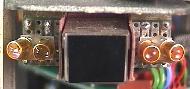
Figure 4. M1’s right half infrared
sensor array |
1.1.3 Contact Sensors
Contact sensors around the periphery of the
basic frame detect forward, side, and reverse contact (6 bits).
In addition, contact sensors are placed on the gripper (2 bits),
since the gripper is the forward-most component of the robot.
The robot also uses the gripper contact sensors to detect and
align with the "gate" before dropping a ball in the
goal area.
1.2 Actuators and Power
1.2.1 Drive Train
M1 uses a two-wheel, differential drive, consisting
of a pair of NEMA 23 frame stepper motors rated at 6.0 volt,
1.0 amp, connected independently to the drive wheels with a toothed
belt and sprocket combination. A third, unpowered caster wheel
completes the basic chassis.
An SGS-Thomson L297/L298 stepper motor bipolar
chopper drive powers the NEMA 23 motors with the current limit
set to 300 mA. Even with this low current limit setting steep
accelerations and decelerations are possible. The battery system
supplies 30 volts with a storage capacity of 600 mA-hr to the
chopper drive which results in an upper limit of step rate in
excess of 6000 half-steps per second. Using stepper motors allows
very accurate drive control, and this particular implementation
appears to result in good performance and low power consumption
at both low and high speeds. |
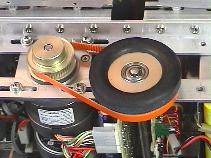 Figure 5. M1’s drive train
 |
1.2.2 Power
A multiple output switcher-based power supply
provides 5 volts and 12 volts for the electronic subsystems. An
additional 5 volt linear regulator is connected to the 12 volt
switcher to provide power to more ripple sensitive, but lower
power demand, electronics. M1 uses a switching power supply because
its efficiency helps to lower power consumption and increase battery
life.
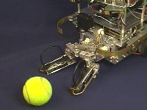
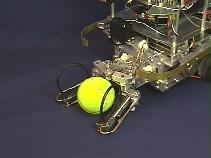
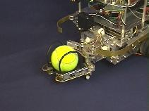
1.2.3 Gripper
A small gripper is mounted on the front of
the robot. In order to capture and keep the self-propelled "squiggle"
ball, a gripper needs to be fast, and keep a firm grip (otherwise
the squiggle ball will wiggle free). Grasping and holding a tennis
ball is comparatively easy. To simplify both construction and
operation, the gripper is built with a single activating motor,
a standard model aircraft servo motor. The single motor actuates
both the grasp and lift actions in sequence – the lift only
happens once the gripper has closed upon the object, regardless
of the size of the object (the tennis balls and squiggle balls
are different sizes). This is accomplished by attaching the motor’s
pull point such that the grasp action is favored over the lift
action. Once the grasp tightens on the ball, continued motor
action lifts the ball. |
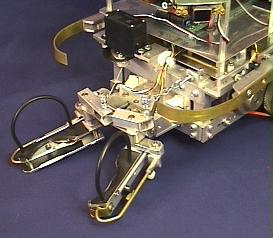 Figure 6. M1’s gripper
 |
|
|
|
Figure 7. Sequence of M1 picking
up a tennis ball |
2. The Robot Software
In many applications, the Cognachrome Vision
System outputs its tracking data to another CPU. However, for
this robot, we decided to interface the robot sensors and actuators
to spare I/O on the vision board, and to write our control software
on the vision board itself. We wrote a fairly simple, reactive
controller for our robot.
2.1 Reactive High-Level Control
With the hard part (the vision tracking) already
taken care of by the vision system’s built-in functions,
we spent several weeks (including a few days at the last minute
at AAAI) writing and testing a simple, reactive control system.
There control system has four basic states:
- Find and approach ball
- Lift ball
- Find and approach goal
- Drop ball
Each state had several sub-states, as shown
in the diagram below:
 Figure 8. Detailed state diagram
for high-level control of M1
Figure 8. Detailed state diagram
for high-level control of M1
2.1.1 Sub-states of interest
Approach ball
Approach ball is active when a ball is seen
in the "Find and Approach Ball" state, and that ball
isn’t already within gripper grasping range. If more than
one ball is seen, the closest ball is generally chosen, with
some hysteresis to prevent oscillation between two balls of similar
distance.
M1 must approach a ball in such a way that
it enters the gripper area from the front. If the ball is directly
to the left or right of the gripper, M1 will back up until the
ball has cleared the gripper’s side. Otherwise, M1 approaches
the ball with a simple feedback loop:
Set M1’s rotational velocity to be proportional
to the angle required to bring the ball directly in front of
M1.
If the ball is "close enough" to
being directly in front of M1, move forward with a velocity inversely
proportional to some function of the angle error.
Follow Wall, in "Find and Approach
Ball"
While the "Follow Wall" sub-state
in the "Find and Approach Ball" state is active, M1
will stop and pivot back and forth at a certain period. (During
the first half of the contest, M1 pivots every 12 seconds, and
during the second half, M1 pivots every 6 seconds.) The purpose
of the wall follow is to help guarantee that the entire region
will be searched. However, in larger rooms, following the wall
isn’t adequate to search the entire room. The pivot behavior
forces M1 to look towards the center of the room every so often,
extending the distance from the wall at which balls can be seen.
Although it isn’t shown in the diagram,
each of the four states has special timeouts to attempt to detect
if the robot isn’t making progress. In this case, the robot
might stop and then start again (in case a stepper motor had stalled),
or might back up (in case the robot had somehow gotten itself
into a tangle of some sort).
2.2 Camera Calibration
M1 uses the vision system to detect balls on
the floor and to detect the blue marking on the gate. Given the
location of a ball in the field of view, and assuming that the
ball is on the floor, M1 can compute the position of the ball
relative to the robot.
M1 uses a fairly wide-angle lens (about 90
degrees). Such a lens results in a pronounced fisheye effect.
Typically, we make the simplifying assumption that the (x,y) coordinates
returned from the vision system map linearly onto a virtual plane
which is perpendicular to the axis of the camera. However, for
this application we decided we needed more accuracy. (Given that
we find ball positions by computing the intersection of the floor
with a line from the camera, and given that the camera is fairly
close to the floor, small angle errors can lead to large position
errors.)
Therefore, we needed to calibrate the camera.
That is, we wanted a function which takes (x,y) coordinates from
the vision system, and returns coordinates in a physical coordinate
system we could deal with. (We actually use spherical coordinates
rather than planar.) We started to deduce the proper mathematical
form of the function describing this mapping for the particular
wide-angle lens we used, but found it was easier (and accurate)
to just use least-squares fits to create two bivariate quadratics
(where the variables are the x and y coordinates), one for the
horizontal angle and one for the vertical angle.
To generate the calibration data for the least-squares
fit, we set up a vision target a distance away from the robot.
We then had the robot pivot from side to side and rotate the camera
up and down in a predefined grid pattern, recording the (x,y)
coordinates of the target given by the vision system at each step.
(The target was far enough away to allow the simplifying assumption
that the camera did not change position, only orientation, despite
the fact the camera was not on the robot’s pivoting axis.)
This method of gathering the data worked well
because of our precise control of the robot's position and camera
angle (made possible in part by using stepper motors).
2.3 Low-level Motor Control
M1 uses stepper motors to drive its wheels.
One problem with stepper motors is that if you try to run them
past their limits (run them too fast, or accelerate or decelerate
too quickly), they will stall. M1 has no stall-detection sensors.
M1 does have stall-recovery behaviors in place (i.e., if the control
software decides that no progress has been made for long enough,
it will slow to a stop, which recovers from the stall), but it
is much better to avoid stalls in the first place.
For this reason, there is a layer of software
between the high-level control and the motors. Whenever the high-level
control software commands a speed, the low-level smoothly accelerates
or decelerates to this speed, within the safety parameters of
the motors.
3. Other Applications for Fast Vision Tracking
Making a winning entry for the AAAI Clean up
the Tennis Court contest was made much easier by having a vision
system capable of quickly tracking targets of interest. The authors
believe that fast vision tracking has the potential to help many
other applications as well. Included here are an assortment of
projects for which the Cognachrome Vision System is currently
used.
3.1 Playing Robot Soccer
Newton Labs entered (and won) the first International
Micro Robot World Cup Soccer Tournament (MIROSOT) held by KAIST
in Taejon, Korea, in November of 1996. We used the Cognachrome
Vision System to track our three robots (position and orientation),
the soccer ball, and the three opposing robots. The 60 Hertz
update rate from the vision system was instrumental in our success;
other teams obtained robot and ball position data in the 2 to
10 Hertz range. This meant that our robots could literally run
circles around their opponents.
Because of the small size of the robots (each
fit into a cube 7.5cm on a side), we opted for a single vision
system connected to a camera facing down on the field, instead
of a vision system in each robot. (In fact, the rules of the
contest required markings on the top of the robot that encouraged
this; all but one of the teams likewise used a single camera
above the playing field. The odd team out decided not to use
vision at all, which severely limited their capability.)
Please see http://www.newtonlabs.com/soccer
for video footage, stills, and technical information about
our entry.
|
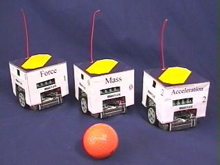 Figure 9. Force, Mass, and Acceleration
are three members of Newton Labs’ world champion robot soccer
team. (Mass is the goalie). In the foreground is the soccer ball
(actually an orange golf ball).
Figure 9. Force, Mass, and Acceleration
are three members of Newton Labs’ world champion robot soccer
team. (Mass is the goalie). In the foreground is the soccer ball
(actually an orange golf ball). |
3.2 Catching Balls and Paper Airplanes
Two Cognachrome Vision Systems were integrated
in the new version of the adaptive robot catching project led
by Prof. Jean-Jacques Slotine of MIT. The project uses an advanced
manipulator and fast-eye gimbals developed under Dr. Kenneth Salisbury
of the MIT AI lab.
Using two-dimensional stereo data from a pair of Cognachrome
Vision Systems, they predict the three-dimensional trajectory of an object
in flight, and control their fast robot arm (the Whole Arm Manipulator, or WAM)
to intercept and grasp the object. (Please see http://www.ai.mit.edu
for more information, and animations of the arm catching various objects).
3.3 Performance Robotics
Performance artist and roboticist Barry Werger
creates performance robotics pieces using Pioneer mobile robots
equipped with the Cognachrome Vision System. By providing the
robot and human players with appropriately colored tags, the robots
can interact with each other, and humans, at a distance in a theatrically
interesting way.
3.4 Group Behavior and Social Interaction of Robots
Maja Mataric,
Barry Werger, Dani
Goldberg, and Francois
Michaud at the Volen Center
for Complex Systems at Brandeis University study group behavior and social interaction
of robots. Along with other robots, they use Pioneer mobile robots outfitted
with Cognachrome Vision Systems.
In conjunction with shorter range or less specific
sensors, such as sonar, the Pioneers use color-based tracking
to help recognize other robots, obstacles, and goals.
Barry Werger says:
"I have combined these two [vision-based
long-range obstacle avoidance and vision-based following of intermittently
blocked objects] to address some of the problems we have in our
mixed robot environment... that is, the Pioneers are faster and
bigger than our other, more fragile robots; the long range avoidance
allows them to keep a safe distance from other robots, even in
fairly dynamic environments, when following a dynamic target.
The vision allows us to make these distinctions very easily,
which the sonar does not."
3.5 Autonomous Docking of Spacecraft
|
The University
of Maryland Space Systems Laboratory and the Kiss
Institute for Practical Robotics have simulated autonomous
spacecraft docking in a neutral buoyancy tank for inclusion on
the UMD’s Ranger space vehicle. Using a composite target
of three brightly-colored objects designed by David
P. Miller, the spacecraft knows its distance and orientation,
and can servo to arbitrary positions around the target. |
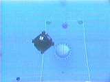 Figure 10. The SCAMP underwater
vehicle positions itself relative to the target
Figure 10. The SCAMP underwater
vehicle positions itself relative to the target |
Figure 11. The target is composed of three
parts: "L", "C", and "R" (left,
center, and right). "X" is the position of the camera.
Note that q is measured in the plane of LRX, not LRC. Adapted from David P. Miller and Anne Wright.
Autonomous Spacecraft Docking Using Multi-Color Targets.
In Proceedings of the 6th Topical Meeting on Robotics,
Monterey, CA, February 1995.

Relationships yielding the 3-dimensional
position of the robot relative to the target, given the 2-dimensional
positions (in camera space) of the three target elements as viewed
from the robot. xl,
yl, xc, yc,
xr, yr are
the positions, in camera space, of the left, center, and right
targets, respectively, as viewed from the robot.
4. Conclusions
The authors have found through the AAAI contest,
as well as many other applications, that a fast vision tracking
system can be a useful sensor for robotic systems. For this particular
contest, fast vision tracking worked especially well. The data
from the vision system were appropriate to the problem at hand,
and allowed us to use a simple reactive system for control. The
vision system’s fast update rate was crucial in being able
to follow and catch the squiggle ball.
We look forward to future opportunities to
apply fast vision tracking to other problems.
References
W. Jesse Hong, Robotic Catching and Manipulation
Using Active Vision. M. S. Thesis, Department of Mechanical
Engineering, MIT, September 1995.
W. Jesse Hong and J.J.E. Slotine, Experiments
in Hand-Eye Coordination Using Active Vision. In Proceedings
of the Fourth International Symposium on Experimental Robotics,
ISER'95, Stanford, California, June 30-July 2, 1995.
David P. Miller and Anne Wright. Autonomous
Spacecraft Docking Using Multi-Color Targets. In Proceedings
of the 6th Topical Meeting on Robotics, Monterey, CA, February
1995.
Randy Sargent, Bill Bailey, Carl Witty, and
Anne Wright. Use of Fast Vision Tracking for Cooperating Robots
in the MIROSOT Micro-Robot World Cup Soccer Tournament. In
Proceedings of Micro-Robot World Cup Soccer Tournament,
MIROSOT ’96, Taejon, Korea, November 9-12, 1996.
The Authors
 Randy Sargent
is President of Newton Research Labs in Renton, WA. He received a
B.S. in Computer Science at MIT, and a M.S. in Media Arts and
Science from the MIT Media Laboratory. Formerly holding titles
of Research Scientist and Lecturer at MIT, he is one of the founders
of the MIT LEGO Robot Contest (a.k.a. 6.270), now in its seventh
year. Randy Sargent
is President of Newton Research Labs in Renton, WA. He received a
B.S. in Computer Science at MIT, and a M.S. in Media Arts and
Science from the MIT Media Laboratory. Formerly holding titles
of Research Scientist and Lecturer at MIT, he is one of the founders
of the MIT LEGO Robot Contest (a.k.a. 6.270), now in its seventh
year. |
 Carl Witty
holds the title of Research Scientist at Newton Research Labs
in Renton, WA. He grew up in Adrian, Oregon, received a B.S.
in Computer Science from Stanford University, and a M.S. in Electrical
Engineering and Computer Science from MIT. A member of the winning
team in the 1991 ACM Programming Contest, his interests include
robots, science fiction and fantasy, mathematics, formal methods
for software engineering, and old movies. Carl Witty
holds the title of Research Scientist at Newton Research Labs
in Renton, WA. He grew up in Adrian, Oregon, received a B.S.
in Computer Science from Stanford University, and a M.S. in Electrical
Engineering and Computer Science from MIT. A member of the winning
team in the 1991 ACM Programming Contest, his interests include
robots, science fiction and fantasy, mathematics, formal methods
for software engineering, and old movies. |
 Bill Bailey
holds the title of Design Engineer at Newton Research Labs in
Renton, WA. He specializes in analog and digital electronics,
software, and mechanical design. When not working on robotics,
he also works at a small software firm in Redmond, WA. Bill Bailey
holds the title of Design Engineer at Newton Research Labs in
Renton, WA. He specializes in analog and digital electronics,
software, and mechanical design. When not working on robotics,
he also works at a small software firm in Redmond, WA. |
 Anne Wright
holds the position of Computer Scientist at NASA Ames Research
Center in Moffet Field, CA, and consultants for Newton Research
Labs in Renton, WA. Anne received B.S. and M.Eng. degrees in
Computer Science from MIT. She also helped lead and develop technology
for the MIT LEGO Robot Contest from 1992 to 1994. Anne Wright
holds the position of Computer Scientist at NASA Ames Research
Center in Moffet Field, CA, and consultants for Newton Research
Labs in Renton, WA. Anne received B.S. and M.Eng. degrees in
Computer Science from MIT. She also helped lead and develop technology
for the MIT LEGO Robot Contest from 1992 to 1994. |
Go to the Cognachrome Vision
System home page